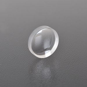
Focusing Lens
The focusing lens belongs to the gradient refractive index lens. It has the characteristics of end-face focusing and imaging, as well as its cylindrical appearance, so it can be used in a variety of different micro-optical systems. There are 5 basic types of focusing lenses: plano-convex, positive concave-convex, aspheric, diffractive and reflective lenses. The last type of reflector is usually an off-axis parabolic reflector, but some system designers use spherical reflectors with small incident angles to accomplish the same function.

Introduction to Focusing Lens
For monochromatic light imaging, the image plane is a plane, and the image quality is consistent on the entire image plane, with small aberrations and no vignetting. For a certain incident light deflection speed corresponds to a certain scanning speed, so linear scanning can be achieved with incident light of equal angular velocity. The deflection position of the incident light beam is generally placed at the front focus of the object space, and the image side principal ray is parallel to the optical axis, which can achieve consistent image quality on and off the axis to a large extent, and improve the uniformity of illumination, and is widely used in laser marking systems.
There are five basic types of focusing lenses: plano-convex, positive meniscus, aspheric, diffractive, and reflective. The last type of reflector is usually an off-axis parabolic reflector, but some system designers use spherical reflectors at low angles of incidence to accomplish the same function.
ZnSe plano-convex lenses, positive meniscus lenses, aspheric lenses, and diffractive optical systems are commonly used transmissive lenses. With the right choice of lens type, almost any focal spot size can be achieved. Aspheric and diffractive lenses produce the smallest focal spots. Applications with lower requirements or longer focal lengths can use plano-convex or positive meniscus lenses. Plano-convex and meniscus lenses are the most cost-effective lenses.
Classification of Focusing Lenses
One way to classify lenses is by the method of beam focusing, which is the two focusing heads that use reflective and transmissive focusing optical systems.
Transmissive lenses are the simplest to use, and the lens focuses the laser beam axially onto the workpiece as it passes through the lens. In most industrial laser systems, the nozzle contains a gas scrubbing function, that is, a gas jet is introduced at the nozzle to help improve the performance of the laser beam and material interaction. At the same time, the high-speed gas flow also plays a role in isolating from the optical system. The gas jet prevents material processing contaminants from entering the nozzle and contaminating the lens surface. The reflective focusing system uses an additional beam deflector and a back focusing mirror (off-axis parabolic reflector). In this condition, there are two additional optical systems, namely the zinc selenide window and the beam deflector. The function of the window is to seal the focusing system above the nozzle.
Transmissive focusing heads have two main advantages, namely, the beam is easy to adjust and allows small deviations such as eccentricity of the beam, that is, the beam is allowed to enter the lens eccentrically or at an angle. Transmissive systems are simpler and use fewer optical components. Reflective lens heads also have two main advantages. The first and most important is that they are used in very high power level applications. They are ideal for applications with power laser systems greater than 4kW. In this case, they produce little thermal lensing effect and are durable in harsh environments such as welding. If a transmissive lens is used instead, it may be quickly contaminated. However, parabolic reflector focusing heads are difficult to adjust. In theory, a parabolic reflector should focus the laser beam to the diffraction limit of the beam. The diffraction limit is the smallest focal spot that can be achieved for a specific laser beam diameter and mode quality. Parabolic reflectors are one of the most difficult reflector systems to adjust, so it is usually difficult to achieve diffraction-limited focusing in high-power laser systems. For welding, a small spot is not always required, so reflectors are suitable for this application.
Advantages of Focusing Lenses
Focusing lenses have the general characteristics of ordinary optical lenses but have their own unique features. It can be used to make ultra-short focal length lenses, and real images can also be formed on the end faces, and it is easy to obtain upright real images of the same size as the object. The difference between self-focusing lenses and ordinary optical lenses is that their focal length and principal plane position change periodically with the length of the lens.
Compared with traditional lenses with the same aperture and focal length, the focal depth of focusing lenses is doubled, and the focal spot size maintains a resolution similar to that of ordinary lenses throughout the focal depth range. The lens is simple to implement and provides a feasible way for large-depth and high-resolution laser processing, and has good application prospects in the field of laser processing. The focusing lens object-image relationship directly shows the effect of this periodic change on the image, and the distance: using the end face as the reference plane avoids the trouble caused by the periodic change of the position of the principal plane with the length of the lens, and can easily determine the reality of the image, so it is desirable in application.
Development direction of focusing lens
In recent years, with the continuous improvement of the performance of high-power lasers, applications such as laser cutting, drilling and precision machining have developed rapidly. However, there is a restrictive relationship between the focal depth and focal spot of traditional lenses. Increasing the focal depth will inevitably cause the focal spot size to expand, which cannot meet the requirements of laser processing in many cases. Therefore, there is a strong demand for focusing lenses with long focal depth and high resolution.
At present, there are many methods to increase the focal depth of focusing lenses. In 1954, McLeod proposed the concept of axicon mirror. After the plane wave is incident on such a device, it becomes a cone wave. After exiting, the spot size can be kept basically unchanged in a large range. However, the light intensity of the formed cone wave on the axis increases linearly with the propagation distance, and is accompanied by violent oscillations, which is not suitable for laser processing. In 1987, Durnin et al. proposed a non-diffraction beam, which can achieve high-resolution beam transmission in a large range. However, the intensity of this type of beam oscillates violently within the focal depth range, which brings great inconvenience to use. In order to solve the problem of intensity variation along the axis, Sochachi et al. proposed to use the energy conservation method to design a logarithmic light cone to achieve a non-diffraction beam, and toe-cutting method to eliminate the intensity oscillation. This method effectively improves the energy distribution within the focal depth range, but the energy utilization rate is too low, which is very unfavorable for laser processing. The method of using an axicon and a non-diffraction beam can increase the focal depth by dozens or hundreds of times. Due to the dispersion of energy, the intensity at the center of the spot is greatly reduced. In actual laser processing applications, it is often only necessary to increase the focal depth by several times on the basis of an ordinary lens to meet the requirements. Using the birefringence effect of crystals, Sanya et al. used a bifocal lens to achieve the extension of the focal depth, but this system requires the use of a polarizer, the power it can withstand is limited, and because there are only two focal points, the increase in focal depth is very limited. In recent years, the use of binary optical elements or specially designed zone plates to achieve long focal depth optical elements has gradually become a research hotspot. This method takes the on-axis light intensity distribution as the objective function and obtains the long focal depth by solving the phase distribution function or light intensity distribution function of the diffraction surface using an optimization algorithm.
Theory of Structural Design of Hyperfocusing System
Figure 1 below is a super-focusing lens system designed by us, which consists of an SPPs coupling wave plate and a focusing lens. Figure 1 is a simplified cross-sectional view, and Figure 2 is a three-dimensional view of the coupling wave plate. It consists of two parts: a thin metal silver film with an annular slit and an annular right-angled triangle prism phase plate. The structure intends to use the coating method to coat a layer of silver film of appropriate thickness on the transparent substrate, and then cover the coated silver film with an optical medium of appropriate thickness, and then use electron beam direct writing or focused ion beam etching according to the designed parameters to produce a coupling phase plate as shown in Figure 2. Then, the aplanatic lens, coupling element and connecting bracket are integrated into a super-focusing system.


In the focusing system designed above, when parallel light shines from the bottom of the silver plate onto the coupling device, it will first excite the SPPs coupling mode through the slit of the silver plate and propagate along the surface of the silver. At the interface between the silver plate and the annular triangular prism, if the wave vector matching condition is met, the SPPs will be efficiently coupled into light waves. The coupled light waves are phase modulated by the annular triangular phase plate and projected onto the aplanatic lens, which is then focused by the lens. The light field distribution modulated by the coupling phase plate directly affects the focusing characteristics of the system.
At the same time, we know that the coupling propagation constant of the SPPs excited by the light wave passing through the slit of the silver plate is related to the width of the slit. The narrower the slit, the larger the propagation constant; conversely, the wider the slit, the smaller the propagation constant. When the slit width increases to more than the wavelength, the coupling effect of the SPPs basically disappears, which is equivalent to an ordinary optical waveguide. Therefore, the coupling propagation constant of SPPs can be controlled by optimizing the size of the slit during design, thereby controlling the phase delay, that is, metal slits of different widths actually correspond to the phase delay of SPPs coupling into the prism. In order to recouple the SPPs excited by the metal silver plate into light wave output, it is necessary to satisfy that the SPPs can be converted into light waves and enter the prism. By setting the height or width of the prism, the angle of the light wave coupled out from each annular right-angled triangular prism can be controlled. Therefore, the optimization of the slit width and the triangular prism can achieve the optimization of the light wave field on the front surface of the aplanatic lens, providing favorable conditions for obtaining a high-quality focused light spot.
ABOUT BORISUN
Hanzhong Brisun Optics Co., Ltd. Is the high precision optical element manufacturer provides customized production of Various optical lenses, including spherical lens, cylindrical lens, optical window, mirror, prism, filter, metal base mirror and other high-precision optical elements. The base materials include various optical glass, fused quartz, calcium fluoride (CaF2), zinc selenide (ZnSe), germanium (GE), silicon (SI), sapphire, metal and other materials. And provide antireflective film, high reflection film, spectroscopic film, metal film and other optical coatings.
Welcome to OEM and Purchasing!
Recent Posts

Send Requests