Analysis of Coaxial Spherical System
Analysis of Coaxial Spherical System
A single refractive spherical surface cannot be used as a basic imaging element (a reflector is a special case of a refractive surface, and a basic imaging element can be formed by a single surface). The basic imaging element is a lens composed of at least two spherical surfaces or aspherical surfaces. For the convenience of processing, most lenses are composed of spherical surfaces. 1. The rotation (or transition) formula of the coaxial spherical system A coaxial spherical system is determined by a series of data: the radius of curvature of each refractive spherical surface; the interval between the vertices of each adjacent refractive surface; the refractive index of the medium between each spherical surface. The calculation of the light path and the calculation of the imaging magnification must be performed after the above structural parameters are given.
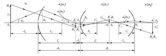
Figure 1: The imaging of an object in the paraxial zone by the first three surfaces of the optical system Figure 1 shows the imaging of an object in the paraxial zone by the first three surfaces of the optical system.

Formula (1) and Formula (2) are applicable to both paraxial light and far-axial light, and can be obtained similarly:

It is also necessary to find the transition formula for the incident height h of the light on the refractive surface:
Using the rotation (transition) formulas of Formula (1) to Formula (4), the optical path calculation problem of any light in the meridian plane of the optical system can be solved. 2. Lach invariant of coaxial spherical system The Lach invariant can be written for each surface:
The Lach invariant J expressed in the above formula is not only an invariant for the object image space of a refractive surface, but also for the object image space of each surface of the entire optical system.
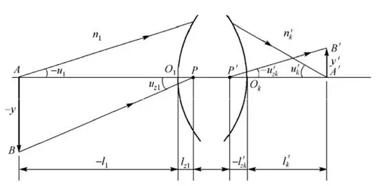
Figure 2: Schematic diagram of two important paraxial optical paths Therefore, it can be used as a calibration formula for the calculation of the two paraxial optical paths shown in Figure 2. The first light: It is emitted from point A on the optical axis of the object plane, with the initial coordinates (l1, u1). The coordinates of its conjugate light after optical path calculation are (l’k, u’k). The second ray: The paraxial ray emitted from the edge point B of the object and passing through the on-axis point P has an initial coordinate of (lz1, uz1). Its coordinates are (l’zk, u’zk) obtained from the optical path. Substitute the Lach invariant:
Substitute the initial coordinates (l1, u1) and (lz1, uz1) of the above two paraxial rays, as well as the coordinates (l’k, u’k) and (l’zk, u’zk) obtained from the optical path calculation into formula (6). If the values on both sides of the formula are equal, it means that the optical path calculation is correct. 3. Calculation of the magnification of the coaxial spherical system For the coaxial spherical system, it is easy to prove that the three magnifications are equal to the product of the corresponding magnifications of each refractive surface using the rotation formula.
(1) Vertical magnification β
(2) Axial magnification α

(3) Angular magnification γ
(4) Relationship between the three magnifications

It can be seen that the relationship between the three magnifications in the coaxial spherical system is exactly the same as that of a single refractive sphere.
Hanzhong Brisun Optics Co., Ltd. Is the high precision optical element manufacturer provides customized production of Various optical lenses, including spherical lens, cylindrical lens, optical window, mirror, prism, filter, metal base mirror and other high-precision optical elements. The base materials include various optical glass, fused quartz, calcium fluoride (CaF2), zinc selenide (ZnSe), germanium (GE), silicon (SI), sapphire, metal and other materials. And provide antireflective film, high reflection film, spectroscopic film, metal film and other optical coatings.
Welcome to OEM and Purchasing!

